Capacity Yard Truck Wiring Diagram: Unlocking the Secrets to Efficient Operations and Maintenance pickup.truckstrend.com
Yard trucks, also known as terminal tractors, shunt trucks, or hostlers, are the workhorses of logistics, tirelessly moving trailers within distribution centers, ports, and intermodal yards. Their continuous operation demands robust performance and, inevitably, meticulous maintenance. At the heart of keeping these crucial machines running smoothly lies an often-underestimated but critically important document: the Capacity Yard Truck Wiring Diagram.
Far more than just a jumble of lines and symbols, a wiring diagram is the intricate blueprint of a yard truck’s electrical nervous system. It maps out every wire, component, connection, and circuit, revealing how power flows and signals communicate throughout the vehicle. For technicians, mechanics, and even operations managers, understanding and effectively utilizing this diagram is paramount for efficient troubleshooting, accurate repairs, enhanced safety, and ultimately, maximizing uptime and productivity. This comprehensive guide will delve deep into the world of Capacity Yard Truck Wiring Diagrams, offering insights, practical advice, and a structured approach to mastering this vital tool.
Capacity Yard Truck Wiring Diagram: Unlocking the Secrets to Efficient Operations and Maintenance
Understanding the Fundamentals: What is a Wiring Diagram?
A wiring diagram is a visual representation of an electrical circuit or system. It uses standardized symbols to depict components, and lines to show the paths of electrical current. For a complex machine like a Capacity yard truck, the diagram encompasses hundreds, if not thousands, of connections across various systems.
Key Elements and Conventions:
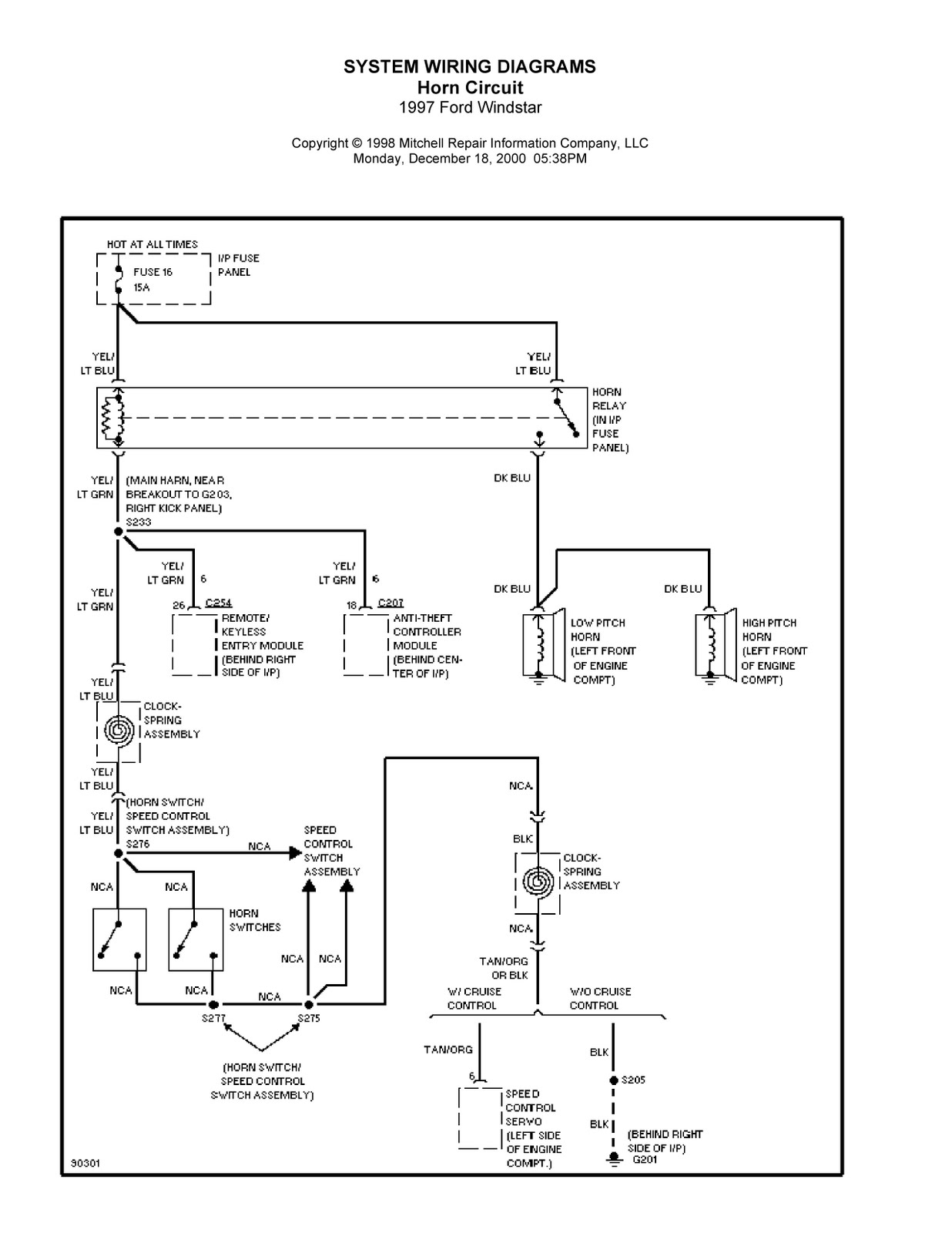
- Symbols: Each electrical component (e.g., battery, fuse, switch, motor, light, sensor, relay) has a specific graphic symbol. Understanding these symbols is the first step to reading any diagram.
- Lines: Represent wires or conductors. Often, these lines are color-coded on the diagram to match the physical wires in the truck, and may include numbers indicating wire gauge or circuit identification.
- Connectors/Splices: Indicate where wires connect to each other or to multi-pin connectors.
- Grounds: Show points where circuits connect to the vehicle’s chassis, forming the return path for current.
- Power Sources: Typically the battery, alternator, or fuse box outputs.
- Legends/Keys: Essential for interpreting the diagram, defining symbols, wire colors, and component abbreviations.
- Circuit Flow: Diagrams are typically laid out to show the logical flow of electricity from power sources, through switches and components, and back to ground.

Key Sections of a Capacity Yard Truck Wiring Diagram
A modern Capacity yard truck’s electrical system is highly integrated. Its wiring diagram is typically organized into logical sections, each detailing a specific subsystem:
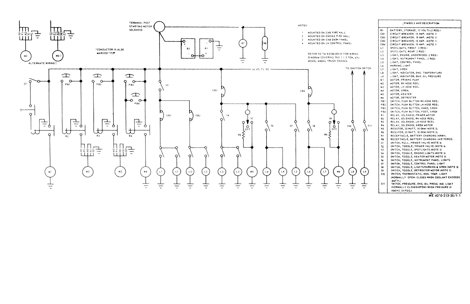
- Power Distribution System: This foundational section outlines the battery, master disconnect switch, main power cables, fuse blocks, circuit breakers, and relay centers. It shows how raw power is distributed to various parts of the truck, often with diagrams of fuse and relay box layouts.
- Starting & Charging System: Details the battery, starter motor, starter solenoid, ignition switch, alternator, and voltage regulator. This section is critical for diagnosing "no-start" conditions or charging system failures.
- Lighting System: Covers headlights, taillights, brake lights, turn signals, hazard lights, work lights, interior cab lights, and often dashboard illumination. It includes switches, relays, and fuse protection for each circuit.
- Engine Control & Management System (ECM/ECU): For electronically controlled engines, this section is highly complex. It maps out the ECM itself, all engine sensors (e.g., crankshaft position, camshaft position, oxygen, temperature, pressure), actuators (e.g., fuel injectors, glow plugs), and communication lines (e.g., CAN bus) that link the ECM to other vehicle modules.
- Transmission Control Unit (TCU): Similar to the ECM, the TCU diagram shows its inputs from various sensors (e.g., speed sensors, shift lever position) and outputs to transmission solenoids, enabling smooth gear changes.
- Braking System (ABS/Air Brakes): While primarily pneumatic, modern air brake systems incorporate numerous electrical components: ABS modules, wheel speed sensors, pressure switches, and warning lights. The diagram illustrates these connections.
- Hydraulic & Pneumatic Control Systems (Electrical Aspects): Yard trucks rely heavily on hydraulics for their fifth wheel lift and sometimes steering. Electrical diagrams show solenoid valves that control hydraulic flow, pressure sensors, and their wiring to the control switches in the cab. Similarly, air system components like air dryer heaters or pressure sensors will be mapped.
- Data Communication Networks (CAN Bus/J1939): Modern yard trucks utilize serial data networks (like J1939, based on CAN bus) to allow various control modules (ECM, TCU, ABS, instrument cluster) to communicate. The wiring diagram will show the data lines (CAN High/Low) and module interconnections.
- Accessory Circuits: This covers non-essential but important systems like the HVAC (heating, ventilation, air conditioning) blower motors, controls, and sensors; windshield wipers and washer; radio/audio system; diagnostic ports (OBD-II or J1939 diagnostic connector); and auxiliary power outlets.

Benefits of Mastering the Wiring Diagram
Proficiency in reading and utilizing a Capacity yard truck wiring diagram offers significant advantages:
- Efficient Troubleshooting: Pinpoint electrical faults quickly and accurately. Instead of guessing, you can logically trace circuits to identify open circuits, shorts, or faulty components.
- Faster Repairs: Once the fault is identified, the diagram guides you directly to the correct wire, connector, or component for repair or replacement, minimizing downtime.
- Enhanced Safety: Ensure proper functioning of safety-critical systems like brakes, lights, and interlocks, preventing accidents and ensuring compliance.
- Preventative Maintenance: Identify areas prone to wear or common failure points by understanding circuit loads and component locations.
- System Modifications & Upgrades: Safely integrate new accessories or modify existing circuits without damaging the electrical system.
- Cost Savings: Reduce labor costs by minimizing diagnostic time, prevent costly component misdiagnosis, and extend the lifespan of the vehicle through correct repairs.
Practical Guide: How to Read and Utilize Your Yard Truck Wiring Diagram
Using a wiring diagram effectively is a skill that improves with practice. Follow these steps:
- Obtain the Correct Diagram: This is crucial. Always use the OEM (Original Equipment Manufacturer) service manual specific to your Capacity yard truck’s model, year, and often its Vehicle Identification Number (VIN). Aftermarket diagrams can be helpful but may lack the precision of OEM versions.
- Understand the Legend/Key: Before tracing any circuit, familiarize yourself with the diagram’s legend. It defines the symbols, abbreviations, wire color codes (e.g., Red/White for a red wire with a white stripe), and potentially wire gauges.
- Identify the Circuit/Component: Locate the specific component or system you are troubleshooting on the diagram. For example, if a headlight isn’t working, find the headlight circuit.
- Trace the Circuit:
- Start at the Power Source: Begin where power enters the circuit (e.g., fuse box, battery).
- Follow the Path: Trace the wire through switches, relays, connectors, and the component itself, all the way to its ground point. Note any splices or intermediate connections.
- Note Wire Colors & Numbers: These are your guides when locating the physical wires on the truck.
- Locate Physical Components: Once you understand the circuit on paper, use the diagram’s component locations (often separate diagrams within the manual) to find the actual wires, connectors, and components on the truck.
- Test and Verify:
- Safety First: Always disconnect the battery before working on electrical components, unless testing live circuits where necessary precautions must be taken.
- Use a Multimeter: Test for voltage (power at various points), continuity (checking for open circuits), and resistance (checking component health or short circuits).
- Diagnostic Tools: For complex systems (ECM, TCU), use an OEM-compatible diagnostic scanner to read fault codes, live data, and perform active tests.
- Document Changes: If you modify a circuit or make a non-standard repair, document it clearly on a copy of the diagram for future reference.
Important Considerations & Potential Challenges
- Complexity of Modern Systems: Today’s yard trucks are highly sophisticated. Their diagrams reflect this complexity, requiring patience and systematic tracing.
- Variations by Model Year/Options: Diagrams can differ significantly between model years, engine types, and optional features. Always verify you have the exact diagram.
- Updates and Revisions: Manufacturers occasionally update diagrams. Ensure your manual is the latest revision.
- Physical Access: Wires and connectors are often bundled, hidden behind panels, or in hard-to-reach areas, making physical tracing challenging.
- Intermittent Faults: These are the most frustrating. A diagram helps by allowing you to systematically test components and connections that might be failing sporadically.
- Safety Precautions: Always disconnect power when working on circuits unless specifically instructed otherwise for testing. Be aware of high voltage circuits and potential for short circuits.
Tips for Effective Wiring Diagram Usage
- Keep it Clean and Accessible: Protect your manuals. Consider laminating frequently used pages or having digital copies on a rugged tablet.
- Use Highlighters/Annotation: When tracing a specific circuit, use different colored highlighters on a printout to keep track of the path. Digital annotation tools are great for PDF versions.
- Invest in Quality Tools: A good digital multimeter, wire strippers, crimpers, and a reliable diagnostic scanner are indispensable.
- Understand Basic Electrical Theory: A fundamental grasp of voltage, current, resistance, and Ohm’s Law will significantly aid in diagnosis.
- Continuous Learning: Attend manufacturer training sessions if available, and regularly review your diagrams to stay proficient.
Table of Key Electrical Components & Associated Costs/Considerations
Understanding the electrical components on a Capacity yard truck extends beyond just tracing wires; it also involves knowing their typical function, lifespan, and replacement considerations. Here’s a table outlining common electrical components you’d find in a wiring diagram and their associated cost/consideration. Please note, costs are highly variable based on OEM vs. aftermarket, new vs. remanufactured, labor rates, and specific truck model.
| Component | Function/Description | Typical Cost Range (Part Only, USD) | Key Considerations |
|---|---|---|---|
| Battery (12V/24V) | Stores electrical energy; provides starting power. | $100 – $300 (per battery) | Deep cycle vs. starting, cold cranking amps (CCA), maintenance-free vs. flooded. |
| Alternator | Recharges battery; supplies power to electrical systems while engine runs. | $300 – $800+ | Output amperage, new vs. remanufactured, pulley type, internal vs. external regulator. |
| Starter Motor | Cranks engine for starting. | $250 – $700+ | Torque rating, new vs. remanufactured, solenoid type, gear reduction. |
| Starter Solenoid | Electrically actuated switch; engages starter motor. (Often integrated with starter) | $50 – $150 | Voltage, current rating, mounting type. |
| Fuses/Circuit Breakers | Protect circuits from overcurrent. | $1 – $20 (per fuse/breaker) | Amperage rating, type (blade, maxi, ATO, etc.), proper replacement is crucial. |
| Relays | Electrically operated switches; allow low-current switch to control high-current circuit. | $10 – $50 | Coil voltage, contact current rating, normally open/closed, pin configuration. |
| ECM (Engine Control Module) | Brain of the engine; controls fuel, ignition, emissions. | $800 – $3000+ (New) | Programmed to VIN, often requires dealer programming/calibration, new or rebuilt. |
| TCU (Transmission Control Unit) | Brain of the transmission; controls shifting. | $500 – $2000+ (New) | Programmed to transmission type, requires calibration after replacement. |
| Sensors (e.g., Speed, Temp, Pressure) | Convert physical conditions into electrical signals for ECUs. | $30 – $200 (per sensor) | OEM vs. aftermarket, specific to location/function, proper calibration. |
| Lighting Assemblies (Headlight, Taillight) | Complete lamp units. | $50 – $300 (per assembly) | LED vs. incandescent, DOT compliance, specific to truck model. |
| Wiring Harness | Bundles of wires for specific sections of the truck. | $200 – $1500+ (per section) | Labor-intensive to replace, often custom for truck model/options, repair vs. replace decision. |
| Diagnostic Tool (Scanner) | Reads fault codes, live data, performs tests. | $300 – $5000+ (Professional) | Compatibility with truck protocols (J1939), software updates, brand specific. |
| Switches (Ignition, Light, Toggle) | Manual electrical control devices. | $20 – $150 | Amperage rating, number of poles/throws, type (rocker, push-button, toggle). |
Concluding Summary
The Capacity Yard Truck Wiring Diagram is not merely a supplementary document; it is an indispensable guide for anyone involved in the maintenance and operation of these vital machines. Mastering its interpretation and application transforms guesswork into precise diagnosis, significantly reduces repair times, enhances safety protocols, and ultimately contributes to the overall efficiency and longevity of your fleet. By investing time in understanding these intricate blueprints and applying the practical advice outlined, you empower your team to keep yard trucks running optimally, minimizing costly downtime and maximizing productivity in the demanding world of logistics. Embrace the wiring diagram – it’s your roadmap to success.
Frequently Asked Questions (FAQ)
Q1: Where can I find the wiring diagram for my specific Capacity yard truck?
A1: The most reliable source is the Original Equipment Manufacturer (OEM) service manual that came with your truck. If you don’t have it, contact Capacity Trucks directly, or an authorized dealer, providing your truck’s model, year, and VIN. Many manuals are available in print or digital (PDF) formats.
Q2: Are all wiring diagrams the same for Capacity yard trucks?
A2: No. Wiring diagrams vary significantly based on the specific model, model year, engine type, transmission type, and optional features installed on the truck. Always ensure you are using the diagram that exactly matches your vehicle’s specifications.
Q3: What basic tools do I need to troubleshoot electrical issues using a wiring diagram?
A3: At minimum, you’ll need a good quality digital multimeter (for measuring voltage, current, and resistance), a set of wire strippers and crimpers, various electrical connectors, and a test light. For more complex diagnostics, an OEM-compatible diagnostic scanner is essential.
Q4: Can I use an aftermarket wiring diagram instead of an OEM one?
A4: While aftermarket diagrams can sometimes be helpful, they may not be as detailed, accurate, or complete as the OEM versions. OEM manuals are designed specifically for your truck and are the recommended source for precise and reliable information, especially for complex or safety-critical circuits.
Q5: How do I know if a wire is broken or has a poor connection using the diagram?
A5: You can use a multimeter to perform a "continuity test" on the wire, as indicated by the diagram. Disconnect both ends of the wire from any power source or component, then touch the multimeter probes to each end. If the meter shows continuity (a very low resistance reading or beeps), the wire is likely intact. An "open circuit" (infinite resistance) indicates a break. For poor connections, check for voltage drop across the connection when the circuit is active.